- 您现在的位置:买卖IC网 > Sheet目录312 > AT27C010-45JU (Atmel)IC OTP 1MBIT 45NS 32PLCC
Atmel AT27C010
4.
Absolute maximum ratings*
Temperature under bias . . . . . . . . . . . . . .-55°C to +125°C
Storage temperature . . . . . . . . . . . . . . . . .-65°C to +150°C
Voltage on any pin with
respect to ground . . . . . . . . . . . . . . . . . . . -2.0V to +7.0V (1)
*NOTICE:
Stresses beyond those listed under “Absolute max-
imum ratings” may cause permanent damage to
the device. This is a stress rating only, and func-
tional operation of the device at these or any other
conditions beyond those indicated in the opera-
tional sections of this specification is not implied.
Exposure to absolute maximum rating conditions
for extended periods may affect device reliability.
Voltage on A9 with
respect to ground . . . . . . . . . . . . . . . . . -2.0V to +14.0V (1)
V PP supply voltage with
respect to ground . . . . . . . . . . . . . . . . . . -2.0V to +14.0V (1)
Note:
1. Minimum voltage is -0.6V DC, which may undershoot to -2.0V for pulses of less than 20ns. Maximum output pin voltage is
V CC + 0.75V DC, which may overshoot to +7.0V for pulses of less than 20ns.
5.
DC and AC characteristics
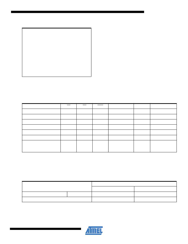
Table 5-1.
Operating modes
X
A9 = V H
Mode/Pin
Read
Output disable
Standby
Rapid program (2)
PGM verify
PGM inhibit
Product identification (4)
CE
V IL
X
V IH
V IL
V IL
V IH
V IL
OE
V IL
V IH
X
V IH
V IL
X
V IL
PGM
(1)
X
X
V IL
V IH
X
X
Ai
Ai
X
X
Ai
Ai
X
(3)
A0 = V IH or V IL
V PP
X
X
X
V PP
V PP
V PP
X
Outputs
D OUT
High Z
High Z
D IN
D OUT
High Z
Identification code
A1 - A16 = V IL
Note:
1. X can be V IL or V IH .
2. Refer to programming characteristics.
3. V H = 12.0 ± 0.5V.
4. Two identifier bytes may be selected. All Ai inputs are held low (V IL ), except A9, which is set to V H , and A0, which is toggled low
(V IL ) to select the manufacturer’s identification byte and high (V IH ) to select the device code byte.
Table 5-2.
DC and AC operating conditions for read operation
Atmel AT27C010
-45
-70
Operating temp. (case)
V CC power supply
Ind.
-40 ? C - 85 ? C
5V ?? 10%
-40 ? C - 85 ? C
5V ?? 10%
3
0321N–EPROM–4/11
发布紧急采购,3分钟左右您将得到回复。
相关PDF资料
AT27C020-55PU
IC OTP 2MBIT 55NS 32DIP
AT27C040-90PU
IC OTP 4MBIT 90NS 32DIP
AT27C080-90PU
IC OTP 8MBIT 90NS 32DIP
AT27C1024-45PU
IC OTP 1MBIT 45NS 40DIP
AT27C2048-55JU
IC OTP 2MBIT 55NS 44PLCC
AT27C256R-45PU
IC OTP 256KBIT 45NS 28DIP
AT27C4096-90PU
IC OTP 4MBIT 90NS 40DIP
AT27C512R-45JU
IC OTP 512KBIT 45NS 32PLCC
相关代理商/技术参数
AT27C010-45JU SL383
制造商:Atmel Corporation 功能描述:EPROM OTP 1M-Bit 128K x 8 45ns 32-Pin PLCC T/R
AT27C010-45JU-T
功能描述:45NS, PLCC, IND TEMP, GREEN 制造商:microchip technology 系列:- 包装:剪切带(CT) 零件状态:在售 存储器类型:非易失 存储器格式:EPROM 技术:EPROM - OTP 存储容量:1Mb (128K x 8) 写周期时间 - 字,页:- 访问时间:45ns 存储器接口:并联 电压 - 电源:4.5 V ~ 5.5 V 工作温度:-40°C ~ 85°C(TC) 安装类型:表面贴装 封装/外壳:32-LCC(J 形引线) 供应商器件封装:32-PLCC 标准包装:1
AT27C010-45LC
制造商:未知厂家 制造商全称:未知厂家 功能描述:x8 EPROM
AT27C010-45LI
制造商:未知厂家 制造商全称:未知厂家 功能描述:x8 EPROM
AT27C010-45PC
功能描述:可擦除可编程ROM 1M bit
RoHS:否 制造商:Maxim Integrated 类型: 存储容量:1024 bit 组织:1 K x 1 接口类型: 工作电流:5 uA 编程电压: 工作电源电压:2.8 V to 6 V 最大工作温度:+ 85 C 安装风格:Through Hole 封装 / 箱体:TO-92
AT27C010-45PI
功能描述:可擦除可编程ROM 1Mb (128Kx8) OTP 5V 45ns RoHS:否 制造商:Maxim Integrated 类型: 存储容量:1024 bit 组织:1 K x 1 接口类型: 工作电流:5 uA 编程电压: 工作电源电压:2.8 V to 6 V 最大工作温度:+ 85 C 安装风格:Through Hole 封装 / 箱体:TO-92
AT27C010-45PU
功能描述:可擦除可编程ROM 1Mb (128Kx8) OTP 5V 45ns RoHS:否 制造商:Maxim Integrated 类型: 存储容量:1024 bit 组织:1 K x 1 接口类型: 工作电流:5 uA 编程电压: 工作电源电压:2.8 V to 6 V 最大工作温度:+ 85 C 安装风格:Through Hole 封装 / 箱体:TO-92
AT27C010-45TC
功能描述:可擦除可编程ROM 1M bit RoHS:否 制造商:Maxim Integrated 类型: 存储容量:1024 bit 组织:1 K x 1 接口类型: 工作电流:5 uA 编程电压: 工作电源电压:2.8 V to 6 V 最大工作温度:+ 85 C 安装风格:Through Hole 封装 / 箱体:TO-92
